Traceability in bearings manufacturing
Fersa Bearings is implementing STREAM-0D solution in the production line. The article provides a detailed explanation of how defective bearings are identified along the production process.
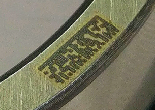
A data matrix is a two-dimensional code consisting of black and white ‘cells’ or dots arranged in either a square or rectangular pattern, also known as a matrix. The information to be encoded can be text or numeric data.
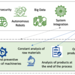
 Nowadays, in the manufacturing field, data matrix systems are linked to reading cameras and robust computer systems to obtain a fast and effective control of the production process. Fersa Bearings is one of STREAM-0D end-users; STREAM-0D solution needs continuous information from the production line in order to feed the models that help operators to anticipate potential defects during the manufacturing process. To do so, information collected in data matrix play an important role.
STREAM-0D solution, combined with many other technologies such as data matrix, for example, allow Fersa Bearings to improve quality ensuring that all supplied parts meet all the required specifications, improving therefore the overall customer value satisfaction.
In this article, Fersa Bearings provides an insight on the procedure needed to define the right size of the data matrix depending on the bearing surface.
The right size
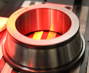
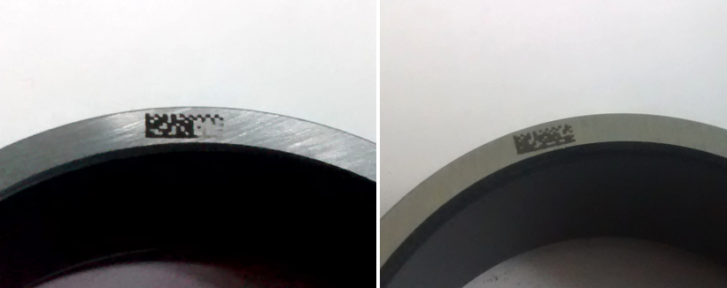
In this specific case, the data matrix must be applied to one of the smallest pieces produced by Fersa: the marking width surface of this piece is 3 mm.
Initially a 2.5×2,5 mm data matrix was selected but, for this kind surface, it resulted too big. Different sizes and shapes of data matrix are then configured to evaluate the marking capacity and its later reading.
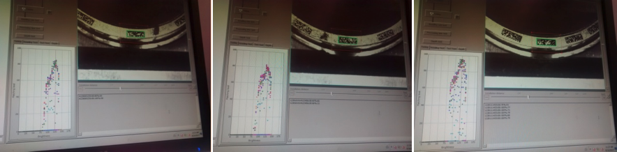
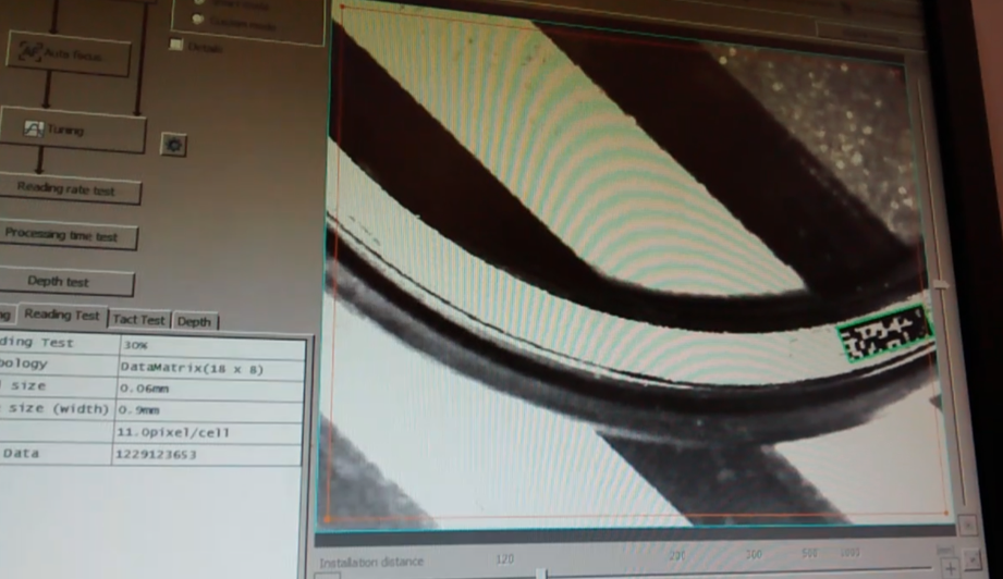
Reading is performed by two different systems: a Datalogic scanner and a Keyence camera. To validate the right data matric, both systems should be able to read it.
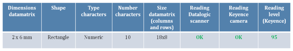
After the tests, the size that best met Fersa’s needs was 2×6 mm. It can be marked correctly on the surface and the reading ability with both systems is correct.
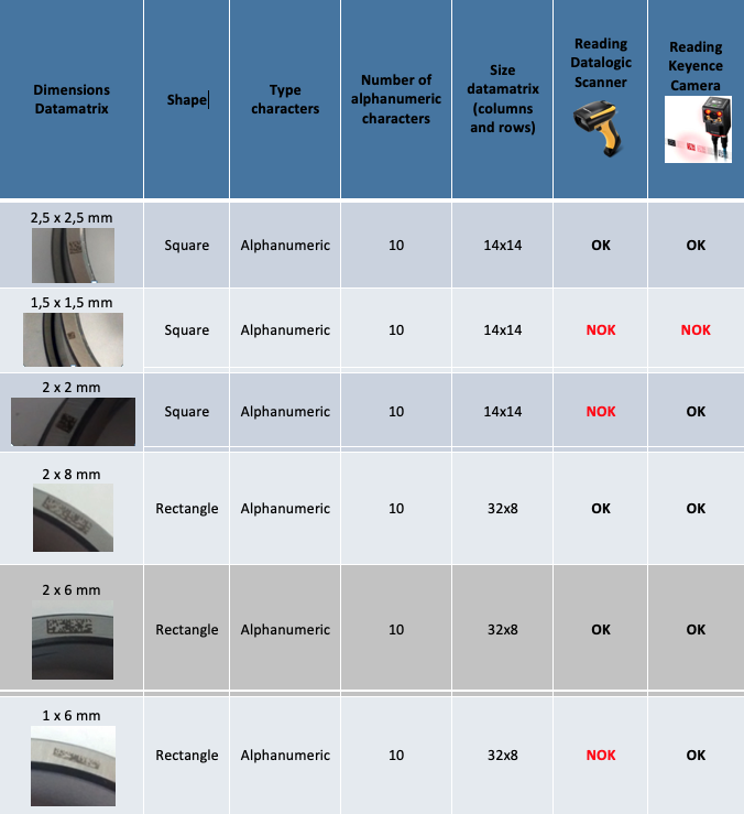
Different tests to select the data matrix.
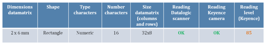
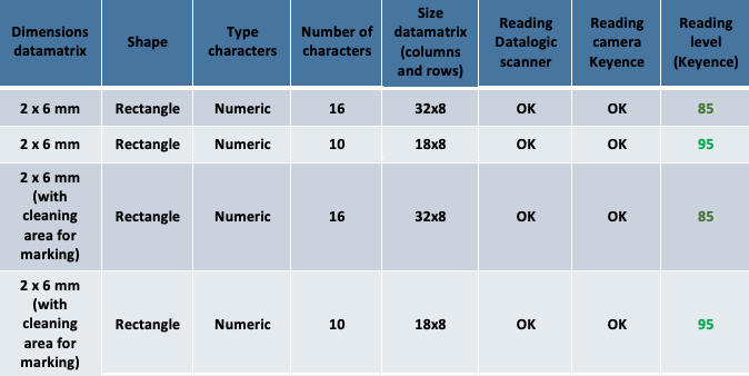
Maintaining the same number of columns and rows, it is possible to mark 16 numeric characters and 10 alphanumeric characters. On the other hand, reducing to 10 numeric characters, also the number of columns and rows decreases. To define the readability level of both options, different tests have been carried out.
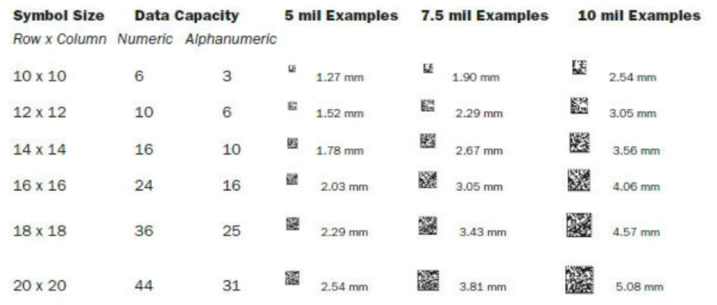
Data matrix capacity.
Changing the number of characters, readability is good (85). Using 10 numeric characters, though, the readability level is even better (95). Both results, 85 and 95, are considered good, as the maximum readability level is 100.
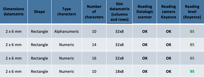
Level reading (Keyence)
The reading system
Following, a list of automatic marking and reading conditions:
- All pieces must be marked with unit codes
- All test are performed on the same luminosity
- Marking of the data matrix is done automatically with 50W laser
- Cycle time of the data matrix is 1,2 seconds
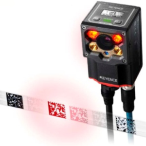
- Reading of the data matrix is done automatically with Keyence camera SR-1000
- Reading is programmed to do 3 cycles. If the camera does not read in these cycles, the piece is discarded (NOK)
- Reading cycle time is 16 seconds
- All data matrix marking are rectangles of 2×6 mm
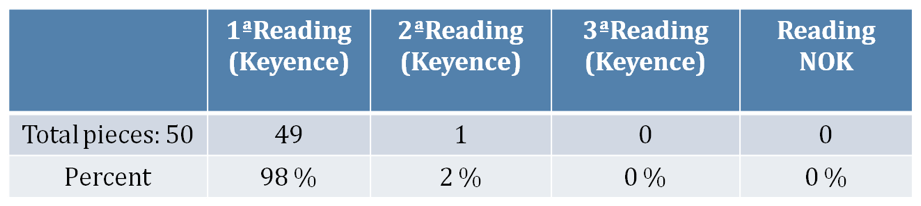
A marking and reading test of 50 pieces with 16 characters numeric has been carried out: one piece was not read during the first try, but the second reading was OK. The marking of this piece does not present any type of incidence.
Also, a marking and reading test of 50 pieces with 10 characters numeric has been performed: this test presented a piece that was discarded due to a data matrix reading errorMarking was faulty and the piece was covered in oil. Once cleaned the piece and passed it under the machine, reading was OK.
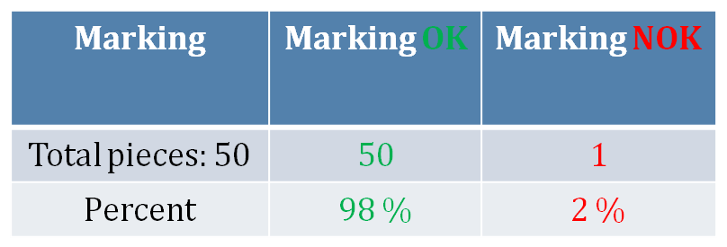

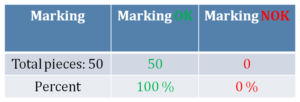
Marking OK v. Marking NOK
A marking defect like the one just experienced, allows a reading level of the Keyence camera that is between 30 and 50. This level is considered very low: in theory, a reading level of above 60 in necessary to ensure a correct reading of the data matrix.
In order to verify the possibility of any improvement in terms of data matrix reading, the tests have been carried out after the marking area was cleaned. Results did not show any further improvement in the readability level.
Level reading (Keyence)
Results of the data matrix marking procedure:
Both markings, 10 and 16 characters were good. The current system assures therefore the correct marking: marking parameters are different to obtain a good data matrix, as the number of columns and rows can differ depending on the width of the area. The cleaning of the pieces from oil is necessary not to have defective markings.
Results of the data matrix reading procedure:
The reading of the 10 and 16 numeric characters is very good. According to the test, the readability level of 10 characters is better than 16 characters because the number of columns and rows is less in the same printing area. Cleaning of the area for marking does not improve the reading.
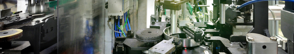
Applications to the manufacturing line
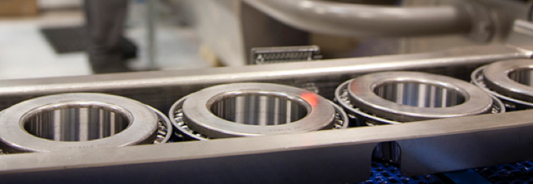
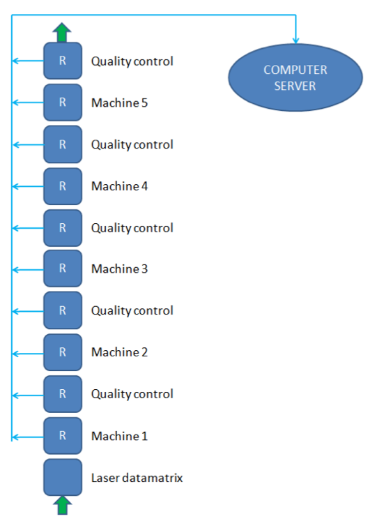 These unitary traceability systems with data matrix allow Fersa Bearings to mark each piece with a unitary code. This code indicates the manufacturing line, part number, time, day, etc. depending on the needs of the company or customer. In each machine of the production line, Fersa installed reading cameras (R). Each piece is therefore verified along all the machines and all the quality controls of the process.
All this information is stored and managed by a computer server. The computer server manages the continuation of the process for every single piece and stores data of the quality controls associated with that data matrix code.
For all the parts that have been manufactured and the ones that are being manufactured Fersa is able to check: data matrix codes, quality register, etc.
This system allows to control the process of the piece along the line, avoiding any type of out of flow because the system would detect that the piece has skipped some process and discard it. Reading the data matrix code it is also possible to determine the issue that is affecting the piece.
—
This article was provided by Fersa Bearings, STREAM-0D project consortium partner.
Follow STREAM-0D on: